UQ Students should read the Disclaimer & Warning
Note: This page dates from 2005, and is kept for historical purposes.
INFS1200 – Assignment 1, part 1
Results | Sample Solution | My Submission
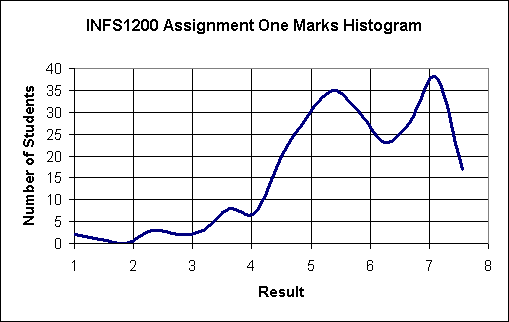
Results
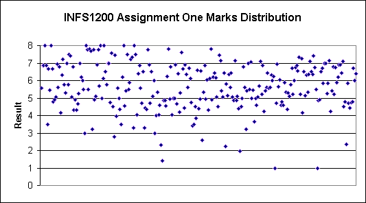
| My Result | 6.35 out of 8 |
| Mean | 5.654198473 |
| Standard Error | 0.083451297 |
| Median | 5.6 |
| Mode | 6.85 |
| Standard Deviation | 1.350777244 |
| Sample Variance | 1.824599164 |
| Kurtosis | 0.575120112 |
| Skewness | -0.625109979 |
| Range | 7 |
| Minimum | 1 |
| Maximum | 8 |
| Count | 262 |
| Confidence Level (95.0%) | 0.164323315 |
Sample Solution
Note that the solution below is “a” possible design of the given universe of discourse. You may have made different design choices in your assignment which may be correct too.
Steps:
1 – Strong Entities | 2 – Weak Entities
| 3 2- 1:1 Relationships | 4 –1:N Relationships
| 5 – M:N Relationships | 6 – Multivalued
Attributes | 7 – n-ary Relationships | 8
– Specialisation
STEP 1 – Strong Entities
The following tables are created:
Company (ABN, Email, URL, Name, Address)
Bus (Reg#, Weight, Type, Model, Make, Seats, Date)
Route (Route#)
City (Postcode, Name, State)
STEP 2 – Weak Entities
The following tables are created:
Branch (Int. Number, ABN, Mgr. Name, Address, Phone, Fax, Email)
Stop (St. no, Postcode)
Trip (Route#, Reg#, Date, Driver, Assistant)
STEP 3 – 1:1 Relationships
none
STEP 4 – 1:N Relationships
Foreign keys are added to existing tables:
Company (ABN, Email, URL, Name, Address, Postcode)
Bus (Reg#, Weight, Type, Model, Make, Seats, Date, ABN)
Trip (Route#, Reg#, Date, Driver, Assistant)
Route (Route#, Start_stop_no., Start_postcode, End_stop_no, End_postcode)
Branch (Int. Number, ABN, Mgr. Name, Address, Phone, Fax, Email, Postcode)
STEP 5 – M:N Relationships
The following tables are created:
Approved_For (ABN, Route#)
Intermediate_stops (Route#, St. no, Postcode)
STEP 6 – Multivalued Attributes
The following tables are created:
Company_phone (ABN, Phone)
Company_fax (ABN, Fax)
STEP 7 – n-ary Relationships
none
STEP 8 – Specialisation
none
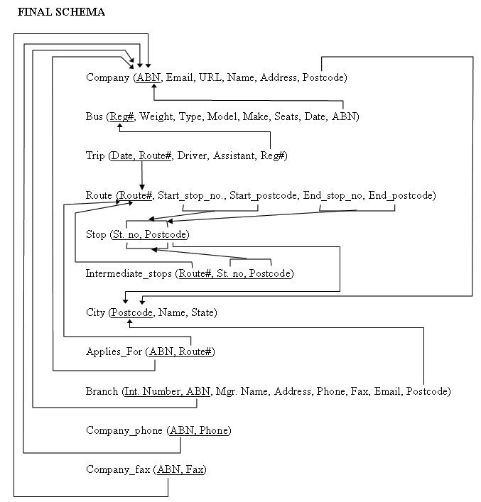
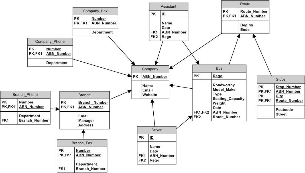
Final Schema
Sample solution may be Copyright © 2003 The University of Queensland, Australia
Sourced from http://www.itee.uq.edu.au/~infs1200//Assignments/Assignment1-Part1-Solution.doc
My Submission
Give specification assumptions (if any), or any special notes/comments that you feel would help us better assess your work
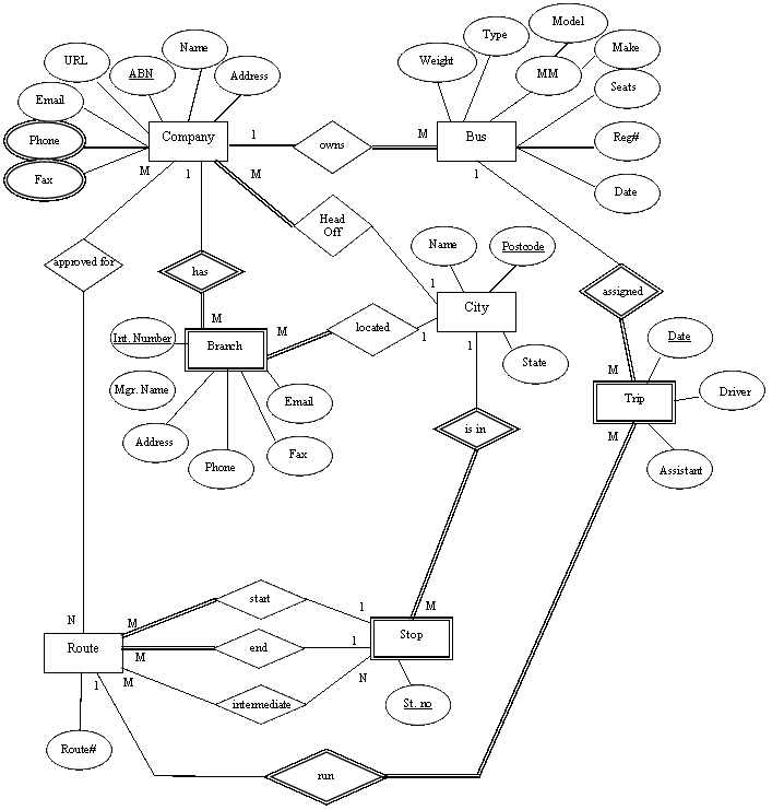
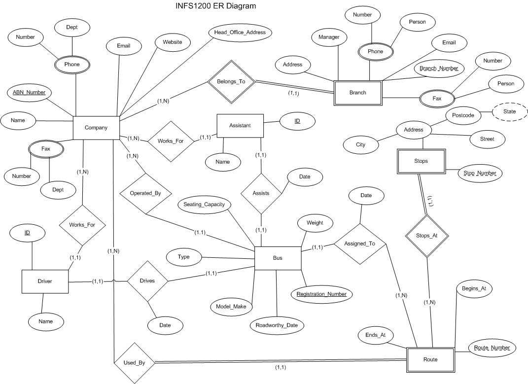
| ER diagram and final relational schema are presented as images. It was found to be too unreliable to use Word drawing tools, as changing font size and various other things would destroy the alignment of elements, so an image was used instead. It was not feasible to use a separate line for each foreign key in the relational mapping, so lines have been combined where possible. A few assumptions were made:
I am not a great admirer of inserting large images into Word documents, as they sometimes do not appear as they should. Should the images in this document are unreadable or otherwise do not work, I have provided the copies in the zip file. Names for entities, relationships and attributes are not necessarily the same on the ER diagram and the relational schema. The min max notation has been used, with double lines to indicate weak entities and their identifying relationship. Total participation is shown by the min max notation and not by double lines, although the lines between a weak entity and its identifying relationship have been shown as double lines. Multi-valued attributes “phone” and “fax” also have double lines. Primary keys have been marked with an underline, and partial keys with a dashed underline. These are not necessarily all possible keys, but only those chosen to identify their entities. Attribute “city” was not included as a key for entity “Stops” in the ER diagram, but while designing the relational schema, it was found to be necessary to use it as part of the key. The ER diagram has not been changed to show “city” as a key, as I did not feel it necessary to use “city” as a key when designing the ER diagram. |
| Official Use Only | ||
| ER (/5) | ||
| Mapping (/3) | ||
| TOTAL (/8) | 6.35 | |
ER Diagram
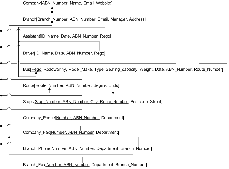
Mapping
Steps taken:
Initial construction and subsequent working was done in pencil and paper, and as I don’t have a scanner, I cannot submit it.
- All regular entities were mapped to relations. All their attributes were added. In the case of composite attributes such as “address” in “stops”, only the simple attributes of the complex attributes were included.
- Weak entities were then added, including as foreign key(s) the primary key(s) from the owner entities. All their attributes were added in the same way as for regular entities.
- Binary relations were then mapped. Primary keys from one relation were included as foreign keys in the other relation – in cases where one relation had total participation, the primary key of the other relation was included in that relation as a foreign key. The attributes on the relations, “date” on relations “drives” and “assists” were then included into the same relation that has the foreign key – in this case “driver” and “assistant”.
- Primary keys were then checked to ensure they were valid and foreign keys incorporated into the primary key in some cases, especially on relation “stops”, where it was necessary to identify stops for specific companies, by city and route number, then by stop number. Different routes could have different numbers for the same stops, and different companies could have the same numbers for different stops. This was not always clear from the ER diagram, and city was not included as a key on the ER diagram.
- Arrows were then added showing foreign keys. This was perhaps the hardest part of the assignment. I have since realised that it is not necessary to add each arrow on its own canvas, and then send that to the back... which would have made it feasible to use Word. However, before I realised that, I drew this, with arrows joining onto other lines to keep the image from becoming too cluttered. An arch is shown when a line passes over another without joining, and a dot is shown when the line joins another. Arrows are placed at the end of the line pointing to the primary key that was used as a foreign key.
End.
The following relational diagram was also used to assist the design of the above, but was not submitted.
All work © Copyright 2003 Ned Martin
07-Sep-2003
18-Sep-2003 - Updated with results